Installing a 4G Antenna
In this guide we take you through the installation of a pair of 17dBi grid antennas on a rural property to provide an ultra fast 4G connection.
Fast Wireless Broadband in Rural Areas
One of the major issues facing many residents in rural communities in regional Australia is the lack of high speed broadband internet services. Many areas have older generation cell towers limited to basic 3G HSPA services, which while providing a usable connection during the day, quickly become congested during peak hours - late afternoon and night. 3G congestion is something most of us are all too familiar with, it's something that affects even those of us with a strong signal - the typical symptom is noticing your connection suddenly drop from full strength to low strength, stall between page loads, or even completely drop out requiring you to disconnect and reconnect manually. While a 3G/Next-G antenna can help by allowing you to lock on to a less congested tower, or by improving signal quality to maximise coding rate, generally there's just not a lot you can do - you're stuck between a rock and a hard place. But there's some good news, Optus and Telstra's continual expansion of high speed 4G wireless broadband means a fast reliable connection might be just over the horizon (literally!). To receive a 4G signal inside your house, you typically have to be within about 3-5km of a 4G cell tower depending on what's between you and the tower. But receiving a 4G signal outside or on your roof is actually quite easy out to about 7-12km, and much further with a strong antenna! When you start talking around the 15-30km range this is where terrain comes into play; the high frequency used to carry 4G doesn't bend particularly well around hills and diminishes quickly through dense foliage. Over these distances you either have to be quite lucky, for example either you or the tower are on a hill, the terrain between is quite flat, or you have to be willing to gain a bit of height by using a large mounting pole.
Step 1 - Assessing the Situation
The first step to solving any problem is identifying the issues and assessing your surroundings. A friend of mine has a property about 14km west of Mackay (north/central QLD) in the cane paddocks which cannot get ADSL or cable Internet. As an avid online gamer his only option was to subsist with high ping rates and unreliable speeds often throwing in the towel and driving into town to use a mate's ADSL. If you've had a quick look at the 4G coverage maps and think you might be in range, the first thing to do is locate your nearest 4G towers. You can do so by following our Cell Tower Locating and Locate a 4G Tower guides which will help you not only pinpoint the 4G tower location, but also work through a basic path profile to determine if there's any hills in the way. Of course Google Earth is only a very basic tool, if you're serious about investigating 4G you should look at having a detailed site assessment done. By using our RF modelling tools we determined that there was indeed a 4G tower in range located on Milton St which appeared to provide a glimmer of 4G between two hills. 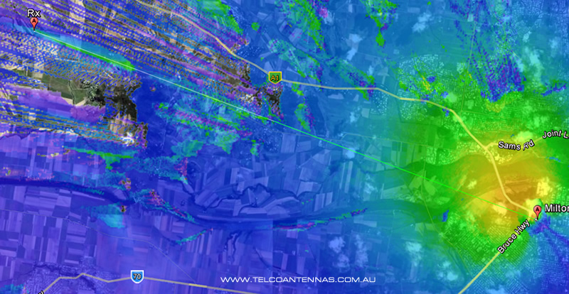
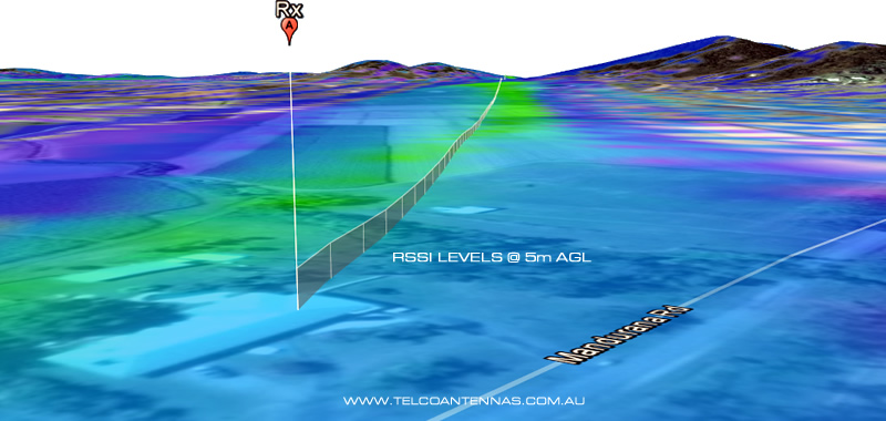
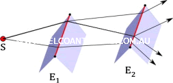 [1] You can see here that signal levels appear surprisingly good, but keep in mind RF propagation just looks at total power level and not whether the signal can be read. In this case the high figure is caused by double-horizon diffraction[1] (additive scattering) which sometimes results in higher RSSI (total power level including noise), but does not improve our RSRP (readable signal). Here's a good tutorial on edge diffraction.
 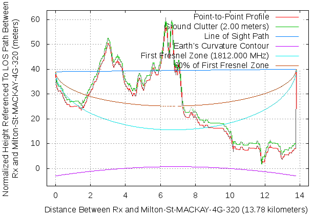 While this location doesn't have line of sight, our propagation model suggests that there is a reasonable potential for 4G. So without further adieu we got stuck into the installation.
The Installation
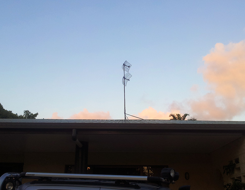
Given the 14km distance and that there was only one cell tower in range the best antennas for the situation were 17dBi grid parabolic antennas. Because his house did not have line of sight to the 4G tower we needed to install the antennas as high as practically possible - in this situation the higher you can raise the antenna the better signal becomes (the clearance distance was 44m above ground!). Some initial tests with a temporary tripod helped us determine whether 4G could actually be obtained, and after aligning to a rough angle we immediately saw speeds between 20-30Mbps with 1-2 bars of service. An old satellite dish mount on the peak of the roof was chosen to be the final installation mount. Some old water pipe lying about made for an excellent extension pole, slotting directly into the satellite mount.
Aligning a 4G Antenna
Because we managed to receive 2 bars of signal it was very likely our modem would switch on MIMO - the use of two antennas to double download speeds. In order for the modem to distinguish between the two data streams on the same frequency the antennas need to be rotated to 45 and 135 degrees to match how the cell tower is broadcasting the slant polarity waves (think polarised sunglasses). You can read more about how MIMO works here. Mounting the antennas in this fashion is a trivial task thanks to the supplied slant-polarity brackets. Now comes the most difficult task - aligning the antennas to the cell tower. While our RF modelling (or your Google Earth profiling) gives an exact azimuth/bearing to point the antennas to, because compasses give magnetic north (not true north) and iPhone/Android compass apps fluctuate about, you often need to align them by hand. The easiest way to do this is simply by trial and error - align the antennas in the general direction and run a speed test via www.speedtest.net. Rotate the antennas by a fraction, and then re-run the speed test. Continue this process making notes of which position produced the fastest speeds, or the most stable speeds. When the antennas are correctly aligned you should see a reasonably consistent speed test - if they're out of alignment you'll notice the speed test jumping about and carrying on (caused by a multipath signal). 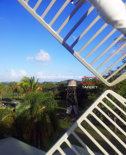 If you're tech-oriented the best way is to use the signal meter figures provided by the modem. We're using a Telstra 320U 4G modem, which has an inbuilt hyperterminal that we can send a few simple commands to, that gives us some very detailed signal level information. Follow this guide to learn how to bring up the modem terminal. The command we're interested in is the AT!GSTATUS? command. The two measures we're interested in most are the RSRP and SINR figures. RSRP is our signal code power (power level of readable LTE signal) and SINR is our signal-to-noise ratio.
 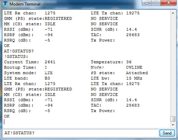 This is from a different installation, our RSRP was -103dBm Because RSRP is a negative value, we want to increase it to be less negative (ie closer to zero). -110dBm is a poor signal, and -80dBm an excellent signal. To align the antennas using these figures, rotate the antenna 1-2 degrees at a time, pausing to run the AT!GSTATUS? command. Once RSRP is maximised you want to make very small corrections to maximise SINR (the higher the number the better).
The Results
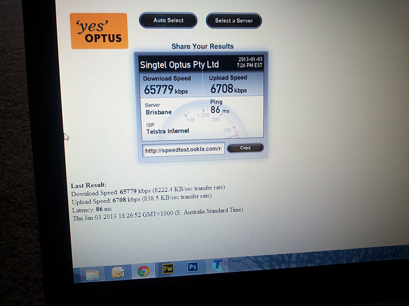
Our speeds weren't particularly great, sitting at around 30Mbps. This was disappointing but it suddenly dawned upon us that the grids were tilting a fraction below the horizon! Because this was a non line-of-sight connection all the radio waves reaching us were being diffracted off the hills, so we tilted the grids about a degree or so upwards and the results were immedate.. 50-65Mbps!
Finishing Up
As a qualified tradie, my friend was more than confident in completing the rest of the installation on his own. We were using two 10m LMR400 extension cables (which were carefully taped to waterproof the connection, and secured in place via zip ties) which were run through the roof by drilling two 11mm holes in the Colorbond roof, running through the crawl space and down into the awaiting 320U modem and Ethernet router. 

[1] Lakulish Antani, Anish Chandak, Micah Taylor, Dinesh Manocha, Efficient finite-edge diffraction using conservative from-region visibility, Applied Acoustics, Volume 73, Issue 3, March 2012, Pages 218-233, ISSN 0003-682X http://www.sciencedirect.com/science/article/pii/S0003682X11002611